
 吉林大学Jilin University
出展技術成果1
出展分野
- 高齢化社会
持続可能な発展目標
目標 11:持続可能な都市とコミュニティ
出展技術テーマ
往復運動に基づいて設計された高空間解像度のウェアラブル3D静脈識別技術
技術の特徴
A Shuttle Roller Coaster Design for Three-Dimensional Imaging with High Spatial Resolution Applicable to Wearable Vein Recognition Devices Compared to 2D images, 3D images with high spatial resolution can provide more information of target objects. A shuttle roller coaster design is proposed to construct a high spatial resolution 3D point cloud by obtaining images in 360 degrees. The design basically comprises of a roller coaster rail, an array of light sources, a spin imaging sensor and a shuttle holder. An application of the proposed design to wrist vein is demonstrated utilizing the vein images in vivo and the 3D images of equivalent vein model in vitro. Based on the experimental results, the spatial resolution of 3D vein imaging can be improved by add more vein images for 3D modeling, which means more vein features can be obtained and the higher spatial resolution 3D vein image can be achieved. Furthermore, this design shows the potential for wearable recognition devices, which will expand the vein recognition applications and contribute to the development of IoT.
応用分野
Biometric
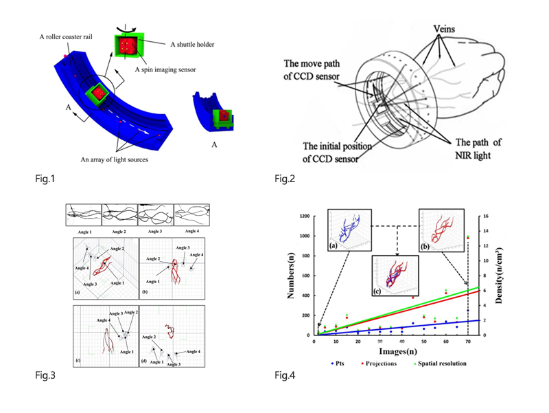
Fig. 1. Schematic design of the shuttle roller coaster structure
Fig. 2. Schematic design of a wrist vein recognition wearing device.
Fig. 3. Part of the images obtained of the vein model from different angles, after graying, enhancement and segmentation, which are shown in the normal view.
Fig. 4: The information and images of the 3D point cloud of the wrist vein model
出展技術成果2
出展分野
- 高齢化社会
持続可能な発展目標
目標 11:持続可能な都市とコミュニティ
出展技術テーマ
受動非接触式MEMS電流センサー
技術の特徴
The proposed sensor is capable of measuring current flowed in a two-wire appliance cord without using any cord separator like that used in Hall-effect based sensor.
The crucial component of the proposed sensor is a cantilever made up of a piezoelectric film and a neodymium micro-magnet integrated on the end. Once the current passes through the two-wire appliance, the magnet attached to the free end of cantilever is subject to the induced magnetic field, then the magnetic force applied to the micro magnet bends the cantilever. And the piezoelectric layer of the cantilever will output a continuous electrical signal under vibration,it is linear with the input current signal theoretically.
The output voltage was determined by the distance of the two-wire appliance cord center to the magnet center, and the maximum change rates of the output voltage reached 4.11% and 9.18% when the change of displacement are ±0.2 mm and ±0.1 mm in x and z direction respectively. The maximum sensitivity can reach 290mV/A with the AC current range of 8 ∼ 200 mA. Furthermore, reducing the size of the micro-magnet might achieve a wider linear range of the applied AC current.
応用分野
Current Detection
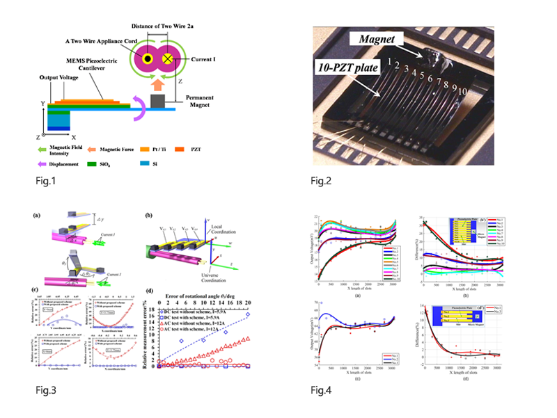
Figure 1 It shows the working principle of the passive Non-contact MEMS Electric Current Sensor.
Figure 2 The fabricated prototype of the proposed passive MEMS DC current sensor with 10 PZT plates and 1 mm3 micro-magnet.
Figure 3 Introduction to the position and orientation correction scheme of the current sensor based on the magnetic piezoelectric cantilever. (a) Definitions of position and orientation errors. (b) Definition of universe and local coordination. (c) and (d) shows the relative measurement errors without and with the scheme.
Figure 4 Analytical results showing the effectiveness with stress-equilibrium consideration, where (a) and (c) showing the correlation between output voltages and the x-dir length of slots with respect to 10 and 3 PZT partition plates, respectively, while (b) and (d) showing the correlation between the difference of the output voltage between piezoelectric plates and the x-dir length of slots with respect to 10 and 3 PZT partition plates, respectively. The insets (b’) and (d’) showing the structural designs with slots of the proposed device with 10 and 3 PZT plates, respectively.